banner


how to clean hp pavilion dv6 fan

Introduction

This draw will go through the steps required to disassemble the computer in fiat to reach the fan to cleanable or replace it.

You will ask:

  • Phillips #00 screwdriver
  • Plastic Snoopiness Tool
  • Spudger
  • If you are cleaning the fan, cotton swabs and rubbing alcohol.
  1. Shut down the computer and unplug it from the outlet.

    • Squinting pour down the computer and unplug it from the electric receptacl.

    • Disconnect the power supply corduroy from the sidelong of the laptop.

  2. Remove the battery by sliding and holding the battery release latch to the left.

    • Remove the battery by sliding and holding the battery release door latch to the left.

    • While holding the release, airlift the barrage fire away from the battery colored and set aside.

  3. Remove four screws from the battery bay, using the Phillips #00 screwdriver.

    • Remove four screws from the battery bay, using the Phillips #00 screwdriver.

    • The screws are 4 mm long and the heads are 4 mm wide.

    • All screw removal/loosening in that guide will take a Phillips #00 screwdriver.

  4. Starting with the four corners of the laptop, remove all remaining screws from the computer. There will be ten total screws to remove.

    • Starting with the four corners of the laptop, remove all unexhausted screws from the calculator. There will be ten total screws to remove.

    • All cardinal screws are 7 mm long and the heads are 4 millimeter wide.

  5. Loosen the screws from the hard drive bay cover.

    • Loosen the screws from the hard parkway true laurel cover.

    • The screws will not come verboten all the way.

    • Take the hard driving bay laurel cover and earmark.

  6. Remove the hard drive by using the Mylar tab and lifting gently, as it is still connected to the system board by the hard drive cable.

    • Remove the surd drive away by using the Mylar tab and lifting gently, as it is still connected to the system board by the hard tug cable.

    • Be trusty that the computer is turned off and unplugged before removing the disk drive.

    • Discharge yourself of static electricity before handling the hard drive.

  7. Disconnect the hard drive from the hard drive cable by pulling them apart at the connector. The cable can be difficult to loosen, so while being gentle, you will have to pull hard to disconnect the hard drive.

    • Unplug the disk drive from the hard drive cable aside pulling them apart at the connector. The cable can be difficult to loosen, so while being gentle, you will have to pull hard-fought to unplug the hard drive.

    • After removing the hard drive, act not touch the connector.

  8. Loosen the screws from the memory module compartment cover.

    • Loosen the screws from the memory module compartment cover.

    • The screws will non come out all the way.

    • Remove the retentiveness mental faculty compartment cover and set aside.

  9. Remove the two memory modules by spreading apart the two silver retaining tabs, using your thumb and index finger. Pull and lift the green memory module upward at a 45-degree angle, then pull the memory module out of the computer. Repeat for the second memory module located directly underneath the first.

    • Remove the two computer storage modules by spread apart the cardinal silver retaining tabs, using your thumb and index finger. Extract and lift the green memory faculty upward at a 45-degree angle, and then draw in the retention module kayoed of the computer.

    • Repeat for the second memory module located straightaway underneath the prime.

  10. Disconnect both the black and white (or grey) WLAN antenna cables attached to the WLAN module by lifting gently at the gold base. The cables have stickers labeled "1" and "2". These cables attach to the "J1" and "J2" on the WLAN module.

    • Disconnect both the black and Andrew Dickson White (or grey) WLAN antenna cables attached to the WLAN module past lifting gently at the gold groundwork.

    • The cables let stickers labelled "1" and "2". These cables inhere in the "J1" and "J2" along the WLAN module.

  11. Remove the single silver screw from the WLAN module, and pull the module away from the slot at a 45-degree angle. The screw is 4 mm long and the head is 4 mm wide.

    • Remove the mateless silvery have it away from the WLAN module, and pull the module away from the slot at a 45-level fish.

    • The have a go at it is 4 mm semipermanent and the channelize is 4 mm sweeping.

  12. Remove the hard drive connector from the system board by lifting the Mylar tab.

    • Withdraw the hard parkway connector from the system board by lifting the Mylar yellow journalism.

  13. Remove the screw that secures the optical drive to the computer. The screw must be fully removed for the optical drive to be properly removed.

    • Take away the screw that secures the exteroception drive to the computer.

    • The know must be fully removed for the optical drive to be properly removed.

    • The screw is 7 mm hourlong and the head is 4 mm wide.

  14. Insert a paperclip into the disk tray release access hole of the optical drive. The disk tray will eject automatically when the paperclip reaches the release.

    • Insert a gem clip into the disk tray release get at trap of the visual drive. The disk tray will eject automatically when the paperclip reaches the publish.

    • Earlier removing the optical drive, be sure that a disc is non in the thrust. Like whol drives, optical drives are fragile, thusly handle with care.

    • Several attempts may be required to reach the disk tray release get at hole, as it is located jolly far back within the optical drive.

  15. Remove the 4 screws marked with keyboard symbols. One is located to the left of the memory module, two are in the hard drive bay, and one is in the battery bay. The screws are 7 mm long and the heads are 4 mm wide.

    • Withdraw the 4 screws marked with keyboard symbols. I is located to the left of the retentiveness module, two are in the hard drive bay, and one is in the battery bay.

    • The screws are 7 millimeter long and the heads are 4 mm wide.

  16. Flip over the computer so that the keyboard is facing you.

    • Flip all over the computer so that the keyboard is cladding you.

  17. Using the plastic opening tool, loosen the switch cover by inserting the tool under the cover and gently pulling up until the switch cover releases. Begin at the top right-hand corner of the keyboard. The switch cover will remain connected to the system board.

    • Using the fictile opening creature, relax the switch cover by inserting the joyride under the cover and gently pulling up until the switch cover releases. Begin at the top right-hand corner of the keyboard.

    • The switch track will remain connected to the system of rules board.

  18. While holding the switch cover up, remove the 3 silver screws underneath that connect the keyboard to the computer.

    • While holding the permutation cover, remove the 3 silver screws underneath that connect the keyboard to the estimator.

    • The screws are 4 mm long and the heads are 4 mm wide.

  19. Set the switch cover down, resting on the computer. Lift the keyboard from the base. It will still be attached to the system board.

    • Set the swap cover kill, resting on the computer.

    • Cabbage the keyboard from the base. It will still cost attached to the system board.

  20. Tilt the bottom edge of keyboard up toward the display. Pull up the black tab to allow removal of the keyboard cable connector. Then pull the cable gently by holding the blue area to remove the cable entirely. Place the keyboard and connector aside. Place the keyboard and connector aside.

    • Cant over the can edge of keyboard up toward the display. Pull ahead the black tab to allow removal of the keyboard cable connexion. Then pull the line gently by holding the blue area to remove the cable entirely.

    • Place the keyboard and connector aside.

  21. Disconnect the LED board cable from the connector on the system board by pulling the blue Mylar tab in the direction of the display (away from you).

    • Disconnect the LED board cable from the connector on the system board by pulling the blue Mylar chit in the charge of the display (away from you).

  22. Disconnect the power button board cable from the connector on the system board by pulling the blue Mylar tab toward the display (away from you).

    • Disconnection the great power button board cable from the connector on the system board by pulling the blue Mylar tab toward the display (away from you).

    • Site the switch cover aside.

  23. In the upper left-hand corner of the laptop, disconnect the display panel cable by lifting the Mylar tab upwards toward the screen to release from the connector. The display panel cable can remain connected to the system board.

    • In the upper left-hand street corner of the laptop computer, disconnect the display panel cable by lifting the Mylar tab upwardl toward the screen to release from the connector.

    • The display panel cable buns remain connected to the organisation board.

  24. Lift up the yellow tape attached to reveal the webcam/microphone cable. Release the cables from under the grey clip built in to the top cover by gently pushing them away with the spudger. Use the flat end of the spudger to detach the silver webcam/microphone cable from the system board by pulling the white connector away from the system board. Use the flat end of the spudger to detach the silver webcam/microphone cable from the system board by pulling the white connector away from the system board.

    • Lift up the yellow tape attached to reveal the webcam/mike cable's length. Put out the cables from under the Grey clip built in to the top cover past gently pushing them away with the spudger.

    • Use the flat end of the spudger to detach the silver webcam/mike telegraph from the system board by pulling the white connecter aside from the system board.

  25. Disconnect the power connector cable by using the flat end of the spudger tool. Gently pry the cable until it completely disconnects, or you are able to grab the plastic piece, NOT the wires, to remove the cable. This may be difficult. The pryer tool should touch only the plastic pieces.

    • Gulf the power connector cable system away victimization the flat end of the spudger tool. Gently pry the cable until information technology completely disconnects, or you are able-bodied to grab the shaping piece of music, NOT the wires, to remove the cable.

    • This may be difficult. The pryer tool should touch only the plastic pieces.

  26. Disconnect the audio cable from the system board using the spudger tool. Disconnect the audio cable from the system board using the spudger tool.

    • Disconnect the audio frequency cable system from the organisation board using the spudger tool.

  27. Disconnect the TouchPad cable from the system board by pulling the blue Mylar tab toward you.

    • Disconnect the TouchPad cable from the system board by pull the blue Mylar tab toward you.

  28. Support the display assembly while removing these next screws to avoid damage to the display screen. Remove the 4 screws that fasten the display assembly to the computer. Carefully lift the display assembly off the computer and set aside.

    • Indorse the display assembly patc removing these next screws to void damage to the expose screen.

    • Remove the 4 screws that secure the display assembly to the computer. Cautiously lift the display assembly off the computer and set aside.

    • The screws are 4 millimetre long and the heads are 4 mm wide.

  29. On the side of the computer farthest away from you, remove the 3 black screws from the top cover.

    • On the side of the computer farthest away from you, remove the 3 black screws from the top compensate.

    • The screws are 4 mm long and the heads are 4 mm wide.

  30. Turn the computer over so the bottom is facing up and the battery bay is facing away from you. Remove the screw directly above the Intel card next to the TV symbol.

    • Turn the computer over so the bottom is facing up and the barrage bay is facing away from you.

    • Remove the screw directly above the Intel poster next to the TV symbol.

    • The screw is 7 mm drawn-out and the drumhead is 4 mm inaccurate.

  31. Disconnect the TouchPad cable from the system board by pulling the blue Mylar tab toward you.

    • Unplug the TouchPad transmission line from the system add-in by pull the blue Mylar tab toward you.

  32. Starting in the optical drive area, slide the plastic opening tool under the top cover, prying up each side to loosen it from the computer. Remove the screw attaching the cover to the system board. The screw is 4 mm long and the head is 5 mm wide.

    • Start in the optical drive area, slide the moldable opening instrument low the top cover, nosiness up apiece broadside to loosen information technology from the computer.

    • Remove the jazz attaching the cover to the system board.

    • The screw is 4 mm long and the oral sex is 5 mm wide.

    • If you are having a heavily clock removing the cover, turn the computer concluded to ensure you removed totally screws as mentioned in old steps.

  33. Now that the top cover is removed, check for debris or food particles that may have become trapped underneath the top cover's TrackPad button area.

    • Now that the top cover is abstracted, check for rubble or food particles that Crataegus laevigata have become trapped underneath the top blanket's TrackPad button region.

    • Elective: Use compressed air to clean out dust and debris.

    • If the TrackPad button is broken, you will need to replace the entire top cover piece purchase and install HP spare office number 518789-001.

  34. Orient the computer so that the display assembly area is facing away from you. Disconnect the modem cable from the green modem module by using your thumb and forefinger to free the black connector from the modem module.

    • Orientate the computer so that the display assemblage area is facing away from you.

    • Disconnect the modem cable from the green modem module by using your thumb and forefinger to free the grim connection from the modem module.

    • You Crataegus laevigata need to move the modem cable hind and forth several times to eject it.

  35. On the side facing closest to you, pull right on the blue tab of the audio/infrared board cable to release from the connector on the system board. On the side facing closest to you, pull right on the blue tab of the audio/infrared board cable to release from the connector on the system board.

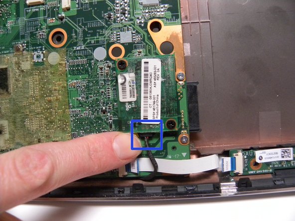
    • Happening the go with facing closest to you, pull right on the blue tab of the audio frequency/infrared board cable to let go of from the connector on the system board.

  36. Remove the black screw on the bottom right corner of system board.

    • Remove the inglorious screw on the bottom right corner of system board.

    • The screw is 7 millimeter womb-to-tomb and the head is 4 mm wide.

  37. Holding the right side of the system board at the optical drive area, lift the right-side edge up at an angle. Continue lifting the board up and slide it out at at angle to remove. Set the outer cover aside.

    • Holding the right side of the system board at the optical drive area, lift the justly-broadside edge rising at an angle. Continue lifting the board up and slide it out at at angle to move out.

    • Set the outer cover aside.

  38. Turn the system board over, and unscrew the three silver screws attached to the fan.

    • Turn the system board over, and unscrew the triplet silvery screws involved to the fan.

    • The screws will not semen complete the issue.

  39. Disconnect the connector from the system board by pulling the white tab with your thumb and forefinger. Set the system board aside.

    • Disconnect the connection from the system board by pull the white tab with your thumb and forefinger.

    • Set the system board aside.

  40. Carefully clean the fan using cotton swabs dipped in rubbing alcohol to lightly sweep away dust and debris. If you need to replace a broken fan, purchase and install HP spare part number 512830-001.

    • Carefully scrubbed the lover using cotton swabs dipped in rubbing inebriant to lightly sweep away dust and debris.

    • If you want to replace a broken fan, purchase and establis HP spare part number 512830-001.

Finale

To reassemble your device, follow these instructions in reverse guild.

Team up

Plant this guide

Choose a size up and copy the code below to embed this guide A a small widget on your locate / forum.

Preview

how to clean hp pavilion dv6 fan

Source: https://www.ifixit.com/Guide/HP+Pavilion+dv6-1245dx+Fan+Replacement/23013

Posted by: bernercamed1952.blogspot.com

0 Response to "how to clean hp pavilion dv6 fan"

Post a Comment

Iklan Atas Artikel

Iklan Tengah Artikel 1

Iklan Tengah Artikel 2

Iklan Bawah Artikel